 Flex II I/O Connections
|
The Flex II system offers great flexibilty to define what is connected to its input, output, and relay
connections. Input line options include a Request-to-Exit, a Door Sensor, a button for an Inter-hub
Signal, two generic switches, two generic buttons, and a deadbolt input. The latter four items
may be renamed to better describe the actual items connected.
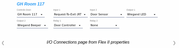
In addition to existing output labels Wiegand LED and Wiegand Beeper, additional output line labels may be created from the Output Labels page. The image above shows a summary for all of the I/O Connections for a selected Flex II Controller hub. It is accessible from the properties of the hub and displays all connected items. Click Edit then click the |
|
|
|
|
I/O Connections may also be viewed and edited for each individual door group and Aux I/O by
clicking the  properties icon for a
Door Group, a Door and I/O Module, a Controller, or an
Expander in the Modules and Groups page. properties icon for a
Door Group, a Door and I/O Module, a Controller, or an
Expander in the Modules and Groups page.
|
| I/O Connections page from Module and Group properties | |
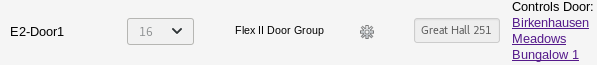
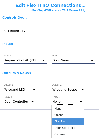
| If a door
is to be connected to a door group, select the door from the list in the
Controls Door: drop down. The door record must be added
before it can be selected from the list. Depending on the
door type, designate a Door Controler or an
Open/Close Signal for the relay.
With these two settings, CyberAudit-Web can configure the Flex Hub to operate the door.
A wiegand reader may be connected to the door group without any additional configuration
on this page. If other inputs and outputs will be used use selector for any available input, output, and relay and select the desired input or label. |
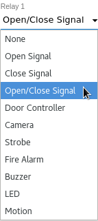 Flex II Relay Output Selector |
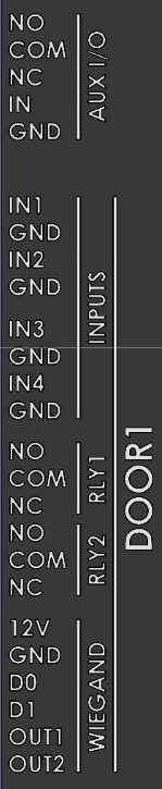
Flex II Input Connection Specifications
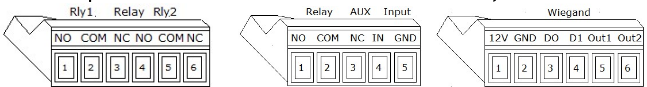
Inputs
All inputs are non-isolated, active pull-down with internal pull-up.
| Connector | Label | Type | Note |
| Input 1 | IN1 | Wet | For optional inputs such as RTE, door sensor, Inter-hub signal button, alarm, strobe, LED |
| Input 2 | IN2 | Wet | same as above |
| Input 3 | IN3 | Wet | Controller only same as above |
| Input 4 | IN4 | Wet | Controller only same as above |
| Tamper Input | TAMP | Wet | Generates a Tamper Closed(609) audit trail event when it transitions to low and a Tamper Open(610) event when it transitions to high. |
| UPS Input | UPS | Wet | Generates a UPS Monitor Closed(611) audit trail event when it transitions to low and a UPS Monitor Opened(612) event when it transitions to high. |
| Aux Input | IN | Wet | Generates a Aux Input Closed(613) audit trail event when it transitions to low and a Aux Input Opened(614) event when it transitions to high. |
Flex II Output Connection Specifications
Outputs
Wet outputs are logic type, open-drain, active pull-down (non-isolated outputs). Relays are isolated outputs.
| Connector | Label | Type | Rating | Note |
| Relay 1 | RLY1 | Dry | 3 amp 30VDC | Door strike, mag lock, or other door latching hardware. Or sounder, camera, or other device. |
| Relay 2 | RLY2 | Dry | 3 amp 30VDC | same as above |
| Aux Relay | AUX I/O | Dry | 3 amp 30VDC | Sounder, camera, alarm, or other device. |
| Wiegand Output 1 | WIEGAND OUT1 | Wet | 100ma 30VDC | Wiegand beeper or LED or other device. |
| Wiegand Output 2 | WIEGAND OUT2 | Wet | 100ma 30VDC | same as above |
